The Peterbilt 389 Service Manual is an essential guide for owners and mechanics, providing comprehensive instructions for maintenance, repairs, and troubleshooting to ensure optimal truck performance and safety.
Overview of the Manual and Its Importance
The Peterbilt 389 Service Manual is a detailed guide designed to assist owners, operators, and mechanics in maintaining, repairing, and troubleshooting the Peterbilt 389 truck. It covers essential systems, components, and procedures, ensuring optimal performance and safety. The manual emphasizes preventive maintenance schedules, diagnostic techniques, and repair best practices. Its comprehensive structure makes it an indispensable resource for extending the truck’s lifespan and preventing costly downtime. Regular use of this manual ensures compliance with manufacturer recommendations, promoting reliability and efficiency in daily operations.

Preventive Maintenance Schedule
The Peterbilt 389 Service Manual outlines a detailed preventive maintenance schedule, ensuring timely inspections and services to maintain performance, safety, and efficiency.
Regular Maintenance Tasks and Intervals
The Peterbilt 389 Service Manual specifies regular maintenance tasks and intervals to ensure optimal performance and safety. These include oil changes every 15,000 to 25,000 miles, lubrication of components, and inspection of tires, brakes, and suspension systems. The schedule also covers drivetrain and electrical system checks, with detailed intervals for tasks like replacing air filters and checking coolant levels. Adhering to these intervals helps prevent breakdowns and extends the truck’s lifespan. Regular servicing ensures compliance with safety standards and maintains fuel efficiency.
Oil Changes and Lubrication Requirements
The Peterbilt 389 Service Manual outlines specific oil change intervals and lubrication requirements to maintain engine health. Oil changes are recommended every 15,000 to 25,000 miles, depending on usage. Synthetic oil is preferred for optimal performance. Differential oil should be changed every 50,000 miles, while hub lubrication is needed every 30,000 miles. U-joints require greasing every 10,000 miles. The manual also specifies NLGI 2 grease for chassis components, ensuring proper lubrication for smooth operation and longevity of the truck’s systems.

Electrical Systems
The Peterbilt 389 electrical system is complex, involving wiring harnesses, circuits, and connectors. The manual provides detailed schematics and troubleshooting guides to ensure proper functionality and safety.
Understanding the Electrical Schematic
The Peterbilt 389 electrical schematic provides a detailed visual representation of the truck’s electrical system, including wiring harnesses, circuits, and connectors. It helps technicians identify components, trace connections, and diagnose issues efficiently. The manual includes step-by-step guides for analyzing the schematic, ensuring accurate troubleshooting of electrical faults. By understanding the schematic, users can locate power sources, ground connections, and relay modules, making repairs safer and more effective. Regular reference to the manual ensures proper system functionality and prevents potential electrical failures.
Troubleshooting Common Electrical Issues
The Peterbilt 389 service manual outlines methods to diagnose electrical problems such as faulty wiring, blown fuses, or malfunctioning sensors. It provides a systematic approach to identify issues using diagnostic tools and the electrical schematic. Techniques include checking power supplies, testing circuits, and inspecting connectors for damage or corrosion. The manual also lists common fault codes and their solutions, helping technicians resolve problems efficiently. Regular troubleshooting ensures reliable operation and minimizes downtime for the vehicle.
Engine Maintenance
Regular engine inspections and component checks are crucial for maintaining performance and longevity. Adhere to the manual’s guidelines for routine maintenance and repairs.
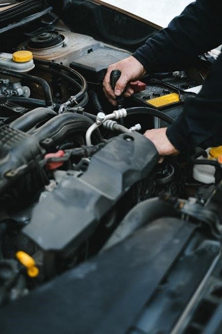
Inspecting and Replacing Engine Components
Regular inspection of engine components ensures optimal performance and prevents costly repairs. Check air filters, belts, and hoses for wear or damage. Inspect cylinder heads, valves, and piston rings for signs of wear. Replace spark plugs and fuel injectors as recommended. Lubricate moving parts and ensure proper coolant levels. Address any leaks promptly, and refer to the manual for torque specifications when replacing components. Proper maintenance extends engine life and maintains efficiency.
Diagnosing Engine Performance Problems
Identify engine issues by checking warning lights and fault codes using diagnostic tools. Monitor performance metrics like power loss, unusual noises, or decreased fuel efficiency. Inspect for coolant or oil leaks, and test compression to detect internal damage. Verify proper air filter condition and exhaust system functionality. Consult the manual for specific troubleshooting steps and repair procedures to address issues effectively and ensure reliable engine operation.

Air Systems
The Peterbilt 389 service manual emphasizes proper air system maintenance, including inspecting the air dryer, tanks, and lines for leaks and damage to ensure optimal performance.
Inspecting the Air Dryer and Tanks
Regular inspection of the air dryer and tanks is crucial for maintaining the Peterbilt 389’s air system efficiency. The manual outlines steps to check for moisture buildup, corrosion, and leaks in the air dryer. Inspect the tanks for dents, rust, and damage, ensuring all connections are secure. Proper maintenance prevents system failure, ensuring reliable braking and pneumatic functions. Follow the recommended schedule to drain moisture and replace desiccant cartridges as needed for optimal performance and safety.
Troubleshooting Air System Leaks
Identifying air system leaks in the Peterbilt 389 requires a systematic approach. Start with a pressure test to locate hissing sounds or visible air escaping from connections. Inspect all hoses, valves, and fittings for cracks or loose connections. Use the manual’s guidelines to check the air dryer and tanks for moisture buildup, which can indicate internal leaks. Drain accumulated moisture and inspect seals for wear. Addressing leaks promptly prevents system pressure loss, ensuring reliable braking and pneumatic functions. Regular maintenance as outlined in the manual is essential to avoid potential safety hazards and performance issues.
Brake Systems
The Peterbilt 389 brake system ensures reliable stopping power, featuring components like brake pads, rotors, and slack adjusters. Regular inspections and maintenance are critical for optimal performance and safety.
Inspecting Brake Pads and Rotors
Inspecting brake pads and rotors on the Peterbilt 389 is crucial for ensuring braking efficiency. Pads should be checked for wear, with replacement needed if thickness falls below 1/8 inch. Rotors must be examined for cracks, scoring, or excessive wear. Any damage or uneven wear patterns require immediate attention to prevent brake failure. Regular inspections help maintain safety and prevent costly repairs.
Adjusting Brake Systems for Optimal Performance
Adjusting the brake system on the Peterbilt 389 ensures safe and efficient stopping power. Start by checking brake fluid levels and inspecting for leaks. Slack adjusters must be calibrated to maintain proper brake shoe alignment. Ensure all components, including camshaft bearings and brake pads, are functioning correctly. After adjustments, test the brakes under controlled conditions to confirm optimal performance. Refer to the service manual for specific torque values and adjustment procedures to ensure reliability and safety on the road.

Transmission and Drivetrain
The Peterbilt 389’s transmission and drivetrain require regular maintenance to ensure smooth power delivery and durability. Check fluid levels, inspect filters, and monitor driveshaft alignment for optimal performance and to prevent premature wear.
Inspecting Transmission Fluid and Filters
Regular inspection of the transmission fluid and filters is crucial for maintaining the Peterbilt 389’s drivetrain health. Check the fluid level using the dipstick, ensuring it reaches the recommended mark. The fluid should be clean and free from contamination or debris. Inspect the filter for dirt or damage, replacing it as specified in the service manual. Proper fluid levels and clean filters ensure smooth gear engagement and prevent overheating. Always use the recommended fluid type and filter replacements to maintain optimal transmission performance and longevity.
Driveshaft and U-Joint Maintenance
Regular inspection of the driveshaft and U-joints ensures smooth power transmission and prevents costly repairs. Lubricate U-joints at each service interval using NLGI grade 2 grease, as specified in the manual. Inspect the driveshaft for any signs of damage, wear, or misalignment. Check U-joints for excessive play or corrosion, replacing them if necessary. Proper maintenance prevents vibration issues and ensures optimal drivetrain performance, enhancing safety and reducing wear on connected components.

Cooling Systems
The Peterbilt 389 cooling system ensures engine thermal regulation, preventing overheating. Regular checks of hoses, coolant levels, and extended life coolant integrity are crucial for optimal function.
Inspecting Hoses and Coolant Levels
Inspecting hoses and coolant levels is vital for maintaining the Peterbilt 389’s cooling system. Check hoses for leaks, cracks, or signs of wear. Ensure coolant levels are within recommended specifications, using a 50/50 mix of extended-life coolant and distilled water. Test coolant freeze points with strips and replace if contaminated. Regular inspections prevent overheating and extend engine life, ensuring reliable performance and reducing repair costs. Always follow manual guidelines for accurate assessments and maintenance.
Preventing Overheating Issues
To prevent overheating in the Peterbilt 389, regularly inspect the cooling system. Check coolant levels, ensuring a 50/50 mix of extended-life coolant and distilled water. Test freeze points using strips and replace coolant if contaminated. Inspect hoses and connections for leaks or damage, and ensure they are secure. Flush the system periodically to maintain efficiency. Monitor the temperature gauge while driving and address any unusual readings promptly. Keep the radiator clean and ensure proper airflow by checking the fan and shroud. Address any leaks or issues immediately to avoid engine damage.
Suspension and Steering
Regular inspection of springs, shackles, and steering components ensures proper handling and safety, while alignment adjustments maintain optimal vehicle performance and reduce wear on tires and suspension parts.
Inspecting Springs and Shackles
Regular inspection of springs and shackles is crucial for maintaining the integrity of the suspension system. Visually examine springs for cracks, worn bushings, or excessive corrosion. Shackles should be checked for wear, misalignment, or loose connections. Ensure all components are securely fastened and properly aligned. Refer to the Peterbilt 389 service manual for torque specifications and adjustment procedures. Proper maintenance prevents premature wear and ensures safe, stable vehicle handling. Always follow safety guidelines when inspecting heavy machinery components.
Aligning the Steering System
Proper alignment of the steering system ensures precise control and reduces tire wear. Use specialized tools to measure toe-in and camber angles, adjusting as needed. Check the drag link, idler arm, and pitman arm for wear or looseness. Tighten all connections to specified torque values. The Peterbilt 389 service manual provides detailed steps for alignment procedures. Regular checks and adjustments optimize steering performance and enhance overall vehicle stability. Always refer to the manual for specific instructions and safety precautions during the alignment process.

Fuel Systems
The Peterbilt 389 service manual details fuel system components, including tanks, lines, and pumps. Regular inspections ensure proper function, efficiency, and emissions compliance. Addressing leaks and wear prevents performance issues and maintains reliability;
Inspecting Fuel Tanks and Lines
Inspecting fuel tanks and lines is crucial for maintaining the Peterbilt 389’s performance and safety. Check for dents, rust, or punctures in the fuel tanks. Ensure all connections are secure and free from leaks. Inspect fuel lines for signs of wear, abrasion, or damage. Verify proper installation of fuel tank straps and brackets. Follow the service manual’s guidelines for pressure testing fuel systems to detect any hidden leaks. Regular inspections prevent fuel system failures and ensure reliable operation. Always adhere to safety precautions when handling fuel components.
Troubleshooting Fuel System Issues
Troubleshooting fuel system issues in the Peterbilt 389 involves identifying common problems like leaks, contamination, or faulty components. Start by inspecting fuel lines and connections for cracks or damage. Check for blockages in fuel filters or injectors, which can restrict fuel flow. Use diagnostic tools to identify error codes related to the fuel system. Consult the service manual for specific repair procedures, such as replacing faulty fuel pumps or cleaning clogged injectors. Proper troubleshooting ensures efficient fuel system operation and prevents costly repairs.

Exhaust Systems
Regular inspections of the exhaust system ensure optimal performance, reduce emissions, and prevent damage. Adhering to safety guidelines is crucial during maintenance and repairs.
Inspecting Exhaust Components
Inspecting exhaust components is crucial for ensuring system efficiency and safety. The Peterbilt 389 service manual outlines procedures for examining the exhaust pipes, mufflers, and clamps for damage, leaks, or corrosion. It’s important to check for any signs of wear or deterioration, as these can lead to performance issues or safety hazards. Regular inspections help maintain the integrity of the exhaust system, ensuring compliance with emissions standards and preventing costly repairs. Always follow the manual’s guidelines for proper inspection techniques and safety precautions.
Ensuring Proper Exhaust System Function
Proper exhaust system function is vital for engine performance and emissions compliance. The Peterbilt 389 service manual provides detailed steps to ensure the exhaust system operates efficiently. This includes verifying that all connections are secure, checking for blockages, and ensuring that the exhaust gases flow freely. Regular maintenance, such as replacing damaged components and cleaning the system, helps prevent issues like backpressure, which can degrade engine efficiency. By following the manual’s guidelines, you can maintain optimal exhaust system performance and extend the life of your truck.

Safety Guidelines
Always follow safety precautions when working with heavy machinery to prevent injuries and ensure proper repairs. Adhere to emergency procedures outlined in the manual for safe operations.
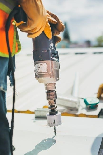
Precautions When Working with Heavy Machinery
When working with the Peterbilt 389, always wear proper PPE, including gloves, safety glasses, and steel-toe boots. Ensure the truck is on level ground with the parking brake engaged and wheels chocked. Disconnect the battery ground strap before starting any repairs. Use jack stands for added safety when working underneath the vehicle. Never attempt repairs near open flames or sparks, and keep a fire extinguisher nearby. Follow all safety guidelines outlined in the manual to prevent accidents and ensure proper repair procedures.
Emergency Procedures
In case of an emergency, such as a fire or system failure, refer to the Peterbilt 389 Service Manual for specific protocols. Evacuate the area immediately and contact emergency services. For fire incidents, use a Class B fire extinguisher rated for fuel and electrical fires. If a breakdown occurs, activate hazard lights and move to a safe location. Always maintain a first aid kit and emergency contact list in the truck. Follow the manual’s guidelines to ensure safety and minimize damage during critical situations.
Troubleshooting Common Issues
The Peterbilt 389 Service Manual provides a detailed guide for troubleshooting common issues, ensuring safe and efficient repairs with adherence to established safety protocols.
Identifying and Addressing Fault Codes
The Peterbilt 389 Service Manual provides detailed guidance on identifying and addressing fault codes to ensure quick and effective troubleshooting. It outlines diagnostic tools and procedures, enabling users to pinpoint issues accurately. The manual covers common fault codes related to electrical, engine, and air systems, offering step-by-step solutions. Regular checks and adherence to the manual’s recommendations help prevent major repairs and maintain optimal vehicle performance. This section is crucial for maintaining operational efficiency and safety.
Resolving Performance Problems
The Peterbilt 389 Service Manual offers comprehensive strategies for diagnosing and resolving performance issues. It covers engine, transmission, and drivetrain diagnostics, providing detailed procedures for troubleshooting. The manual emphasizes regular inspections and maintenance to prevent issues and optimize efficiency. By following the outlined steps, users can identify root causes, address problems effectively, and restore peak performance. This section is vital for maintaining reliability and minimizing downtime.
The Peterbilt 389 Service Manual is a comprehensive resource for maintaining and repairing your truck. Following its guidelines ensures optimal performance, safety, and longevity of your vehicle.
Summarizing Key Maintenance Practices
Regular maintenance is crucial for the Peterbilt 389, including oil changes, lubrication, and inspections of brakes, tires, and electrical systems. Adhering to the service manual ensures optimal performance, prevents breakdowns, and extends vehicle lifespan. Routine checks of air dryers, coolant levels, and drivetrain components are essential. Proper lubrication and timely replacements of worn parts help maintain efficiency and safety. Following the manual’s guidelines ensures compliance with safety standards and minimizes repair costs, keeping the truck in peak condition for years.
Importance of Regular Servicing
Regular servicing for the Peterbilt 389 is vital for maintaining its performance, reliability, and longevity. It helps prevent major repairs by identifying potential issues early. Consistent maintenance ensures compliance with safety regulations and reduces downtime. Properly serviced trucks experience improved fuel efficiency and lower operational costs. Regular inspections and timely part replacements also enhance driver safety and overall vehicle functionality. Adhering to the service manual’s recommendations ensures the truck operates at its best, making it a critical part of responsible ownership and fleet management.

Additional Resources
Explore official Peterbilt websites, forums, and service centers for genuine parts, updated manuals, and expert advice to complement your Peterbilt 389 service manual.
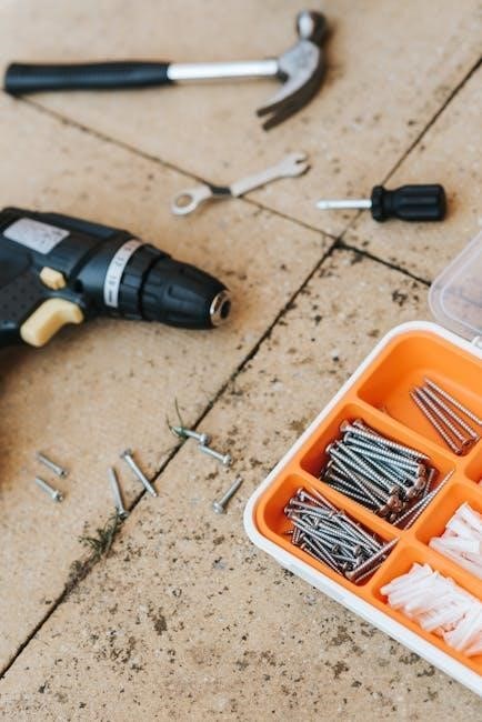
Recommended Tools and Equipment
The Peterbilt 389 Service Manual PDF recommends specific tools and equipment for effective maintenance and repairs. Essential tools include a torque wrench, multimeter, air compressor, and pneumatic tools. Additionally, diagnostic software and a wiring diagram are crucial for troubleshooting electrical issues. Safety gear like jack stands and wheel chocks is also necessary. These resources ensure comprehensive servicing, helping to maintain the truck’s performance and longevity. Proper tools and equipment are vital for safe and efficient maintenance procedures. Always refer to the manual for specific tool requirements.
Online Forums and Communities
Online forums and communities are invaluable resources for Peterbilt 389 owners and technicians. Platforms like TruckersForum and Peterbilt enthusiasts’ groups offer discussions on maintenance tips, troubleshooting, and service manual interpretations. These communities provide real-world insights and solutions from experienced users, fostering collaboration and knowledge sharing. They also serve as hubs for updates on the latest tools and techniques, ensuring users stay informed about best practices for their vehicles; Engaging with these forums can enhance diagnostic and repair capabilities, complementing the service manual effectively.